[Note: This is a article about the syllabus on this topic for A level (H2) physics in Singapore. The O level physics syllabus is a simpler version of this. ]
When we think of electricity in everyday life, we normally think of lights, computer, electric kettle, smart phones, and all the nice, convenient things that we take for granted. Not many - would think about the electricity that makes these things work.
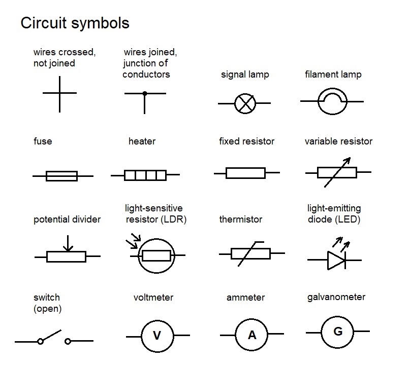
The image above shows a list of the common, basic components that make electricity so useful in our life. It also happens to be the list of electric circuit components that we need to learn in the physics syllabus.
A very simple circuit to switch on a light bulb may look something like this.
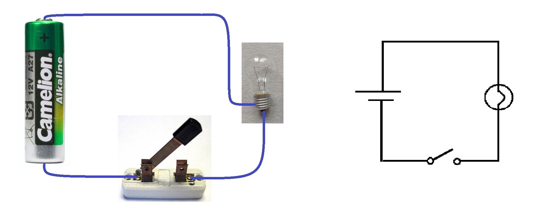
The picture on the left is the actual circuit. The one on the right is the circuit diagram. The switch on the left looks a bit similar to its symbol on the right in this example. The light bulb and battery look quite different. With some practice, it should be quite easy to recognise what the symbols represent.
The following is a list of photos of the more common components.
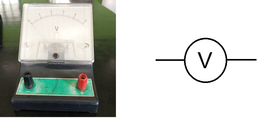
Voltmeter
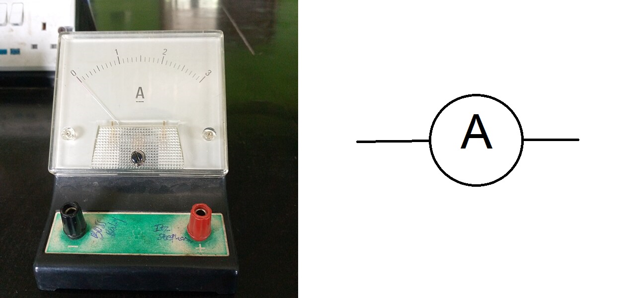
Ammeter
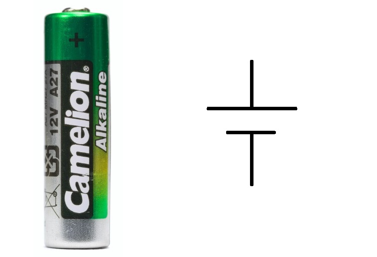
Cell
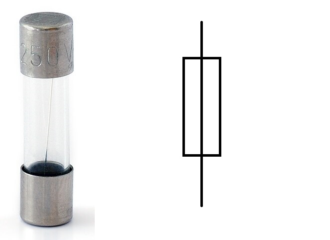
Electrical fuse
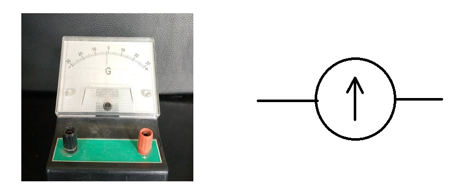
Galvanometer
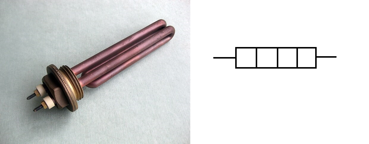
Heating element
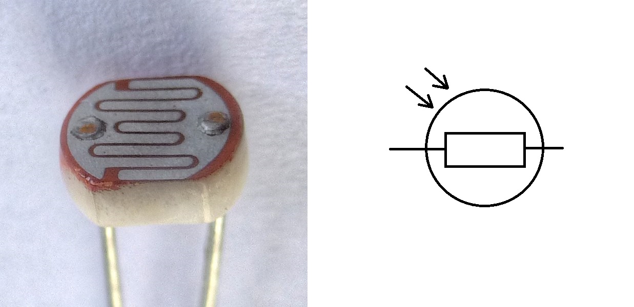
Light dependent resistor
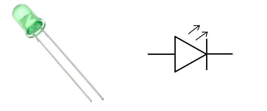
LED
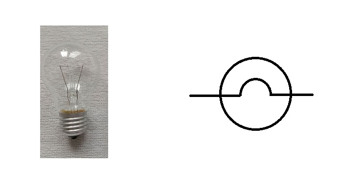
Light bulb
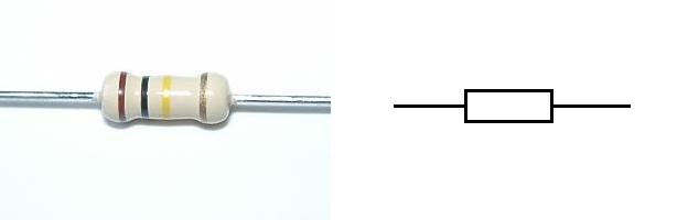
Resistor
Signal lamp

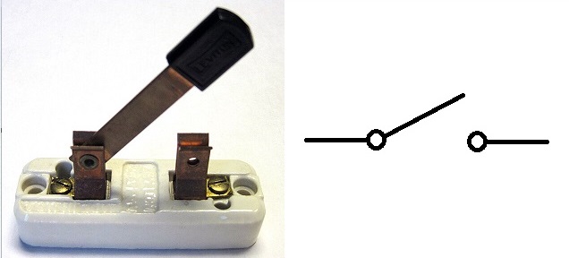
Switch
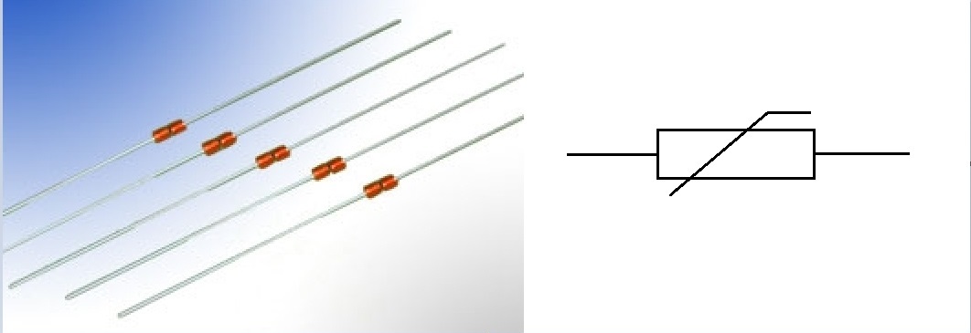
Thermistor
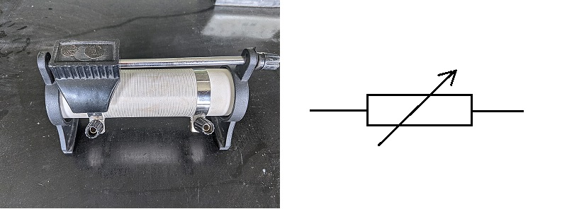
Variable resistor
Recognising the symbols and knowing their functions is the easy bit. The tricky part is to calculate the the currents and voltages in different parts of a cicrcuit.
No, not just that circuit above. Exam questions would tend to be a bit more complicated. Like this.
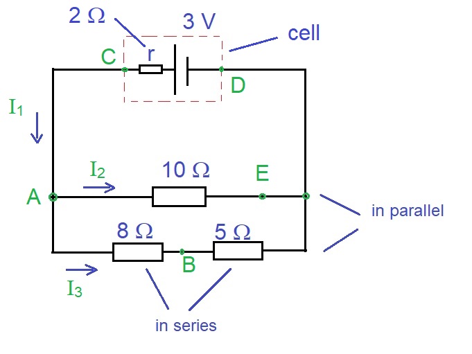
where we may be asked to find the currents I1, I2, I3, voltages between any two points on the circuit, and so on.
And a tricky bit is when the question asks you to find the internal resistance of the cell, r.
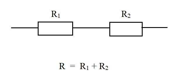
The basic method to calculate the combined resistance of a number of resistors (like in the circuit above) is the make use of these two formulae.
When there are two resistors in series like this, they have the same effect as a single resistor given by the formula below.
When they are in parallel like this, they have the same effect as a single resistor given by the formula below.
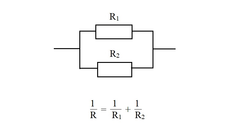
And when they are more complicated like the example above, it is usually possible to find the answer by applying these two formulae repeatedly.
Next, we look at the idea of a "potential divider". A simple battery we can buy from a shop would have a fixed voltage, like 1.5 V. If I need more, I can stack more in series. But what if I need an awkward voltage like 0.7 V or if I need to change the voltage often?
You may wonder why we want to do that. If we can adjust the voltage, we can use this to change the brightness of a lamp, or change the volume of a radio.
One simple way to do this is to add a variable resistor in the circuit. This allows us to change the voltage or current by changing the resistance. Using thie method, the brightness or volume can be adjusted.
This method can be automated. Suppose there is a circuit component that drops quickly in resistance when temperature goes up. We can make a circuit with this component in series with a fire alarm. When it is cold, there is little current because resistance is high. When it is hot, the resistance drops a lot and the electric current increases, causing the alarm to ring.
This can be used as a fire alarm!
In a similar way, we can make a use of a light-dependent resistor. This decreases in resistance when there is light. If connected in series with a light bulb and a battery, the current would increase when it gets dark. This can be use to automatically switch on street lights at night!
Finally, I shall just mention the use of a potentiometer. In electronics, this word can just mean the variable resistor as described above. But in physics, it also means a special circuit that can be used to measure the EMF of a battery.
EMF, or electromotice force, is not a force. It is the voltage of a cell or battery that a voltmeter measures if there is of there is no internal resistance. But there is usually some internal resistance for a typical battery. The battery has a small current when connected to a normal voltmeter. So some voltage used to overcome the internal resistance, and the voltmeter can only measure the remaining voltage.
So the voltmeter just measures the EMF minus the voltage drop due to internal resistance of the battery. This means the EMF measurement is not very accurate.
What is there is a way to measure the EMF without having toe take any current from the battery? That is where this special potentiometer method comes in.
Remember the "potentiometer" mentioned earlier that is used to adjust the volume of a loudspeaker or brightness of a lamp?
Instead of connecting to a loudspeaker or lamp, we can connect it to a battery in reverse. We then adjust the potentiometer until the galvanometer shows zero current.
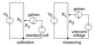
(Note: A galvanometer is an ammeter that can measure current in either direction. An ammeter only measures current in one direction. Of course, you can reconnect the ammeter the other way round if you need to - just a bit troublesome if the current keeps changing direction.)
You can learn these concepts and more at Dr Hock's maths and physics tuition.